Saturday, 27 June 2020

Pump power calculation

Hydraulic Pump Power

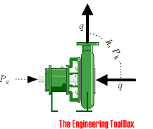
The ideal hydraulic power to drive a pump depends on
  • the mass flow rate the
  • liquid density
  • the differential height
Pump power - si imperial units
- either it is the static lift from one height to an other or the total head loss component of the system - and can be calculated like
Ph(kW) = q ρ g h / (3.6 106)
        = q p / (3.6 106)                  (1)
where
Ph(kW) = hydraulic power (kW)
q = flow (m3/h)
ρ = density of fluid (kg/m3)
g = acceleration of gravity (9.81 m/s2)
h = differential head (m)
p = differeential pressure (N/m2, Pa)
The hydraulic Horse Power can be calculated as:
Ph(hp) = Ph(kW) / 0.746                                  (2)
where
Ph(hp) = hydraulic horsepower (hp)
Or - alternatively
Ph(hp) = qgpm hft SG / (3960 η)                              (2b)
where
qgpm = flow (gpm) 
hft = differential head (ft)
SG = Specific Gravity (1 for water)
η = pump efficiency

Example - Power pumping Water

1 m3/h of water is pumped a head of 10 m. The theoretical pump power can be calculated as
Ph(kW) = (1 m3/h) (1000 kg/m3) (9.81 m/s2) (10 m) / (3.6 106) 
    = 0.027 kW

Shaft Pump Power

The shaft power - the power required transferred from the motor to the shaft of the pump - depends on the efficiency of the pump and can be calculated as
Ps(kW) Ph(kW) / η                                     (3)
where
Ps(kW)  = shaft power (kW)
η = pump efficiency

Tuesday, 13 December 2016

AC INDUCTION MOTOR

Induction motors are the most commonly used electrical machines. They are cheaper, more rugged and easier to maintain compared to other alternatives


Parts of an Induction Motor

                              An induction motor has 2 main parts; the Stator and Rotor. The Stator is the stationary part and the rotor is the rotating part. The Rotor sits inside the Stator. There will be a small gap between rotor and stator, known as air-gap. The value of the radial air-gap may vary from 0.5 to 2 mm.

Construction details of a Stator

A Stator is made by stacking thin-slotted highly permeable steel laminations inside a steel or cast iron frame. The way the steel laminations are arranged inside the frame is shown in the following figure. Here only few of the steel laminations are shown. Winding passes through slots of the stator.


Effect of 3 Phase Current Passing Through a Stator Winding

When a 3 phase AC current passes through the winding something very interesting happens. It produces a rotating magnetic field (RMF). As shown in the figure below a magnetic field is produced which is rotating in nature. RMF is an important concept in electrical machines
To understand the phenomenon of a rotating magnetic field, it is much better to consider a simplified 3 phase winding with just 3 coils. A wire carrying current produces a magnetic field around it. Now for this special arrangement, the magnetic field produced by 3 phase A.C current will be as shown at a particular instant.
Fig.4 Magnetic field produced around the simplified winding and a single wire
The components of A.C current will vary with time. Two more instances are shown in the following figure, where due to the variation in the A.C current, the magnetic field also varies. It is clear that the magnetic field just takes a different orientation, but its magnitude remains the same. From these 3 positions it’s clear that it is like a magnetic field of uniform strength rotating. The speed of rotation of the magnetic field is known as synchronous speed.
Fig.5 Rotating magnetic field produced over simplified winding

The Effect of RMF on a Closed Conductor

Assume you are putting a closed conductor inside such a rotating magnetic field. Since the magnetic field is fluctuating an E.M.F will be induced in the loop according to Faraday’s law. The E.M.F will produce a current through the loop. So the situation has become as if a current carrying loop is situated in a magnetic field. This will produce a magnetic force in the loop according to Lorentz law, So the loop will start to rotate.
Fig.6 Effect of RMF on a closed conductor


The Working of an Induction Motor

A similar phenomenon also happens inside an induction motor. Here instead of a simple loop, something very similar to a squirrel cage is used. A squirrel cage has got bars which are shorted by end rings.
Fig.7 Squirrel cage rotor which is the most commonly used one in induction motors.
A 3 phase AC current passing through a Stator winding produces a rotating magnetic field. So as in the previous case, current will be induced in the bars of the squirrel cage and it will start to rotate. You can note variation of the induced current in squirrel cage bars. This is due to the rate of change of magnetic flux in one squirrel bar pair which is different from another, due to its different orientation. This variation of current in the bar will change over time.
Fig.8 RMF produces a torque on rotor as in the simple winding case
That's why the name induction motor is used, electricity is induced in rotor by magnetic induction rather than direct electric connection. To aid such electromagnetic induction, insulated iron core lamina are packed inside the rotor.
Fig.9 Thin layers of iron lamina which are packed in rotor
Such small slices of iron layers make sure that eddy current losses are at a minimum. You can note one big advantage of 3 phase induction motors, as it is inherently self starting.
You can also note that the bars of a squirrel cage are inclined to the axis of rotation, or it has got a skew. This is to prevent torque fluctuation. If the bars were straight there would have been a small time gap for the torque in the rotor bar pair to get transferred to the next pair. This will cause torque fluctuation and vibration in the rotor. By providing a skew in the rotor bars, before the torque in one bar pair dies out, the next pair comes into action. Thus it avoids torque fluctuation.

The Speed of Rotation of a Rotor & the Concept of Slip

You can notice here that the both the magnetic field and rotor are rotating. But at what speed will the rotor rotate?.To obtain an answer for this let's consider different cases.
Consider a case where the rotor speed is same as the magnetic field speed. The rotor experiences a magnetic field in a relative reference frame. Since both the magnetic field and the rotor are rotating at same speed, relative to the rotor, the magnetic field is stationary. The rotor will experience a constant magnetic field, so there won’t be any induced e.m.f and current. This means zero force on the rotor bars, so the rotor will gradually slow down.
But as it slows down, the rotor loops will experience a varying magnetic field, so induced current and force will rise again and the rotor will speed up.
In short, the rotor will never be able to catch up with the speed of the magnetic field. It rotates at a specific speed which is slightly less than synchronous speed. The difference in synchronous and rotor speed is known as slip.

Energy Transfer in the Motor

The rotational mechanical power obtained from the rotor is transferred through a power shaft. In short in an induction motor, electrical energy is enters via the Stator and output from the motor,the mechanical rotation is received from the rotor.
Fig.10 Power transfer in a motor
But between the power input and output, there will be numerous energy losses associated with the motor. Various components of these losses are friction loss, copper loss, eddy current and hysteresis loss. Such energy loss during the motor operation is dissipated as heat, so a fan at the other end helps in cooling down the motor.

Advantages and disadvantages of induction motors

Advantages

The biggest advantage of AC induction motors is their sheer simplicity. They have only one moving part, the rotor, which makes them low-cost, quiet, long-lasting, and relatively trouble free. DC motors, by contrast, have a commutator and carbon brushes that wear out and need replacing from time to time. The friction between the brushes and the commutator also makes DC motors relatively noisy (and sometimes even quite smelly).

Disadvantages

Since the speed of an induction motor depends on the frequency of the alternating current that drives it, it turns at a constant speed unless you use a variable-frequency drive; the speed of DC motors is much easier to control simply by turning the supply voltage up or down. Though relatively simple, induction motors can be fairly heavy and bulky because of their coil windings. Unlike DC motors, they can't be driven from batteries or any other source of DC power (solar panels, for example) without using an inverter (a device that turns DC into AC). That's because they need a changing magnetic field to turn the rotor.

Saturday, 10 December 2016

Shpboard Alternators- Synchronising, Paralleling and load sharing

How are Generators Synchronized on a Ship?
                     
                  Synchronization of generators is an activity that is carried out quite often on ship. It is a prerequisite that each and every engineer on the ship knows the procedure thoroughly. In emergencies, the engineers are required to carry out the process manually in extremely limited amount of time.

 Introduction
               
                  It's a known fact that marine generators are the heart of any type of ship. Maritime law requires that every ship should have at least two generators. Nowadays all the ships have around 2-3 generators on board. More number of generators are used to facilitate load sharing and to prevent wear down due to excessive load.
             Maintenance of generators at regular interval of time is extremely important. In this article we will learn the process of generator synchronization when multiple machines are required or one of the generators needs to the stopped and the other started in its place
Say for example if a ship has three generators on board, two are used under normal working conditions and one is kept as stand-by.                
              Whenever a requirement to service a running generator arises , the standby generator is brought in line and the desired generator is taken off line. For bringing the standby generator in line, the generator is synchronised with the other running generators.

The main things that are kept in check for synchronizing a generator are :
Frequency
Voltage
Load
Phase

Let's have a look how the synchonization of generators is done manually

Generator Synchronization Procedure- Before starting

A step by step method for synchronizing generators in provided below.

1. When a decision of synchronizing generators in taken, first the bridge should be notified about the scheduled activity
2.Start the generator that has to be synchronized. Before starting, prime the engine with fuel using hand pump. Make sure the engine block heater is turned off.
3. Open the air valve and then turn on the engine.
4. Once the engine starts, check if the oil pressure and cooling water pressure is adequate. Check if the cooling water pump is working properly by feeling the pipes. Once the check is done, close the air valves.

Synchronizing procedure

1. Once the engine starts running properly, synchronization is carried out.
2. In the Engine control room, Check the pressure gauges.
3. On the generator control panel, check if all the ground lights are working properly with adequate brightness.synchroscope 2.291110319 std
4. Also check the synchronizing relays for open position. Bring the running or the lead generator to the desired optimum parameters: 480 volts and 60 hertz
5. Bring the generator that is to be synchronized(0n-coming) to the desired parameters. Now turn on the synchronizing relay and keep a close look at the needle.
6. The needle in the synchroscope will move at a varying speed initially. Adjust the speed of the generator by obtaining a steady slow motion of the needle in the clock wise direction.
7. Once the needle is moving at a steady speed, depress the breaker close button when the needle has traveled three-fourth of its way. Energize the breakers when the needle reaches a position similar to the 11' o clock position of a clock.
8. After doing this, check the parameters of the on-coming generator. They should be same as those of the leading generator. i.e 480 Volts and 60 hertz

 After synchronizing

After the main job of synchronizing, the following steps are to be carried out.
1. Change the governer control to the off-going generator.
2. Now the load shown in the guages by this generator should be removed off the system as soon as possible before it starts acting as load(reverse power). This can be done by quickly pulling the trip breaker as soon as the generator goes off-line.
3. Once the generator is offline, stop the engine using a toggle switch.
4. After turning off the engine, turn on the engine block heater.
5. At the end, take a proper look at the control panel guages for adequate pressure and even distrubution of load.
           It must also be noted that load distribution can be adjusted by varying the fuel supply to the generator via its governor but for current sharing to be equal you would need to vary the excitation current which changes the power factor of the generator.

Wednesday, 7 December 2016

Purifiers - Importance of Parameters - Start Stop Procedures

Centrifugal Oil Purifiers - Starting and Stopping Procedures


               We all know that centrifuges are an important type of auxiliary equipment on board ships and that they are classified into two operating functions.
     
      One is Clarifier, which separates solids from liquids.
      Other type is a Purifier, which separates liquids of different density.

The Purifier operates on the principle of separation by centrifugal force. But in order to optimize the purification process, certain parameters should be adjusted before purifier is started. Out of those parameters, very important parameters are...

 1. Feed inlet oil temperature, 
2. Density of Oil, 
3. R.P.M of the rotating bowl,
 4. Back Pressure, 
5. Throughput of oil feed.

Insight Of the Parameters...!

1. Feed inlet oil temperature: Before entering the purifier, the dirty oil passes through the heater, which increases the temperature, thus reducing the viscosity of the oil to be purified. The lower the viscosity, the better will be the purification.

2. Density of Oil: As the dirty oil entering the purifier is heated to reduce the viscosity, the density also reduces. The lower the density, better the seperation.

3. R.P.M of the rotating bowl: If the purifier has not achieved full rpm(revolutions per second), then the centrifugal force will not be sufficient enough to aid the seperation.

4. Back Pressure: The back pressure should be adjusted after the purifier is started. The back pressure varies as the temperature, density, viscosity of feed oil inlet varies. The back pressure ensures that the oil paring disc is immersed in the clean oil on the way of pumping to the clean oil tank.

5. Throughput of oil feed: Throughput means the quantity of oil pumped into the purifier/hr. In order to optimize the purification, the throughput must be minimum.

Pre-checks before starting a Purifier...!

Before starting a Purifier, following checks are very essential:

1. If the Purifier is started after a overhaul, then check all fittings are fiited in right manner. The bowl frame hood locked with hinges.

2. Check the Oil level in the gear case. Ensure that it is exactly half in the sight glass. Also ensure the sight glass is in vertical position, as there is a common mistake of fixing it in horizontal position.

3. check the direction of rotation of the seperator, by just starting and stopping the purifier motor.

4. Check whether the brake is in released position.

Starting a Purifier...!

1. Ensure the lines are set and respective valves are open. Usually the lines are set from settling tank to service tank.

2. Start the purifier feed pump with the 3-way re-circulation valve in a position leading to settling tank.

3. Open the steam to the heater slightly ensuring the drains are open so that the condensate drains. close the drains once steam appears.

4. Start the Purifier.

5. Check for vibrations, check the gear case for noise and abnormal heating.

6. Note the current (amps) during starting. It goes high during starting and then when the purifier bowl
picks-up speed & when it reaches the rated speed, the current drawn drops to normal value.

7. Ensure the feed inlet temperature has reached optimum temperature for seperation as stated in the Bunker report & nomogram ( bunker delivery note gives the density of the fuel and using this we can get the seperation temperature and gravity disc size from the nomogram)

8. Now check whether the bowl has reached the rated speed by looking at the revolution counter. The revolution counter gives the scaled down speed of the bowl. The ratio for calculation can be obtained from the manual.

9. Now, after the bowl reaching the rated rpm, check for current attaining its normal value.

De-sludge procedure:

10. Open the Bowl closing water/Operating water, which closes the bowl. (Ensure sufficient water is present in the operating water tank)

11. Now after 10 seconds, open the sealing water to the bowl.

12. The sealing water should be kept open till the water comes out of the waste water outlet.

13. Once the water overflows throught the waste water outlet, stop the sealing water.

14. Now open the de-sludge water/bowl opening water. (this is done to ensure the bowl has closed properly). During de-sludge we can hear a characteristic sound by the opening of the bowl.

15. Repeat the steps 10, 11 ,12 & 13.

16. Open the 3-way re-circulation valve such that the dirty oil feed is fed into the purifier.

17. Wait for the back pressure to build up.

18. Check for overflowing of dirty-oil through waste water outlet & sludge port.

19. Now adjust the throughput to a value specified in the manual. Correspondingly adjust the back pressure too.

20. Now the purifier is put into operation. Change over the clean-oil filling valve to service tank.

After-checks & stopping of purifier...!

Checks after starting the purifier during regular watches:

1. Adjust the throughput, back pressure, temperature of feed inlet if necessary

2. gear case oil level, motor amps, general leakages, vibration have to be monitored

3. De-sludge every 2 hours for heavy oil purifiers & every 4 hours for lubricating oil purifiers.( refer manual or chief engineer instructions)

Stopping of Purifiers:

1. De-sludge the purifier after stopping the feed inlet.

2. shut down the steam inlet to the oil.

3. Stop the purifier after filling up the bowl with water.

4. Apply brakes and bring up the purifier to complete rest.

5. If any emergency, the purifiers has emergency stops, on pressing it, will stop the purifiers immediately shutting off the feed.


Main Engine Rating.. Courtesy marine insight

Effective Power: The Power available at the output side of the engine i.e. at crankshaft flange of the engine which connects it with the flywheel and rest of the intermediate shaft
Rated Power: It is the continuous effective power provided by the manufacturer of the engine for a desired or rated RPM of the crankshaft. Rated power includes the loads which acts on the engine due to auxiliary system running from the engine power
Indicated Horse Power: It is a theoretical power calculated with a formula
                                                               PxLxAxN /4500
   
Where
P- Mean indicated pressure of the cylinder
L- Stroke of the engine
A-  Cross Sectional Area of the engine cylinder
N- Speed of the engine in RPM
4500 is a constant for conversion.of kgm-min to hp metric units
              In this calculation, the frictional losses are not considered. Since it is calculated from indicated pressure of  the engine, it is called Indicated Horse Power or IHP and used for calculating mechanical efficiency of the engine
Shaft Horse Power: The power delivered by the engine to the propeller shaft is measured by an instrument known as torsion metre which is available on board.
Break Horse Power: This is the power measured at the crankshaft with the brake dynamometer and is always higher than the shaft horse power. This is because the power available at shaft accounts for frictional and mechanical losses.
Gross Power: Continuous effective power provided by the manufacturer for a given RPM using defined number of auxiliaries at normal service running condition without any overloading of the engine.
Continuous Power: It is the BHP measured at the power take off end when the engine is running at continuous safe operation range outside any time limit. This is provided by the supplier.
Overload Power: It is the power excess of effective power than the rated power for a short period of time, when the same auxiliaries are used under similar service condition for limited period.
Minimum Power: The guaranteed minimum or lower most power value by the manufacturer for an approximate crankshaft RPM is the minimum power of the engine.
Astern Output Power: The maximum power engine can generate when running in the astern direction at safe condition.
Maximum Continuous Rating or MCR: It is the maximum power output engine can produce while running continuously at safe limits and conditions.
Standard Rating: This is the power output of the engine at normal service speed which gives the highest economical efficiency, thermal and mechanical efficiency. At this speed, the wear down of the engine is at the minimum rate.

Friday, 13 May 2016

Marine Air Compressors


What is emergency air compressor ?

It is a small compressor independently driven by a prime mover having power supply from emergency switch board. They are also driven by diesel engines.
It must be fitted to press up the emergency air bottle and to start auxiliary engine of a dead ship.
It has no connection between the main air bottle.

What are the safety devices in air compressors on ships ?

Bursting discs are fitted on the cooler shells (At water side).
Relief valves are fitted to discharge side for every stages.
Moisture drain valve (unloader) are fitted at each cooler side.
Cooling water failure alarm.
Low L. O pressure alarm and trip.
Delivery air high temperature alarm on after cooler outlet (Max 93° C)

What are the normal parameters of air compressor ?

LP discharge pressure: 4 bars
HP discharge pressure: 30 bars.
Intercooler inlet air temperature: 130 ° C
Intercooler outlet air temperature: 35 °  C
After cooler inlet air temperature: 130 ° C
After cooler outlet air temperature: 35 °  C

Type of intercooler and after cooler ?

Intercooler is single pass type
After cooler is double pass U-tube type

Purpose of unloder valve (moisture drain valve) in air compressor ?

At starting this valve must be opened, this reduced the starting torque for the machine and clear out any accumulated moisture and oil in the system.

What would be effect of suction valves of an air compressor having too much lift ?

The valve will be late in closing and this would reduce the volumetric efficiency of the machine.
The valve experience greater force and therefore are more liable to break.

Causes of reduced volumetric efficiency of air compressor ?

Greater bumping clearance.

Sluggish opening and closing of suction and delivery valves.
Insufficient cooling water that effect of high air temperature.
Dirty or partially chocked suction air fitter.

Difference between relief valve, bursting disc and fusible plug ?

Pressure relief valve

Excess pressure is released by opening the valve.
It opens at 10% over working pressure.
Valve lift is proportional to excess pressure build up.
Valve setting pressure can be altered by spring tension.

Bursting disc

Pressure is released by bursting the disc.
It permanently damaged.
It burst at setting pressure.
Setting pressure cannot be altered in place.

Fusible plug

When the air temperature from compressor is high (above 105 ° C) pressure is released by melting (fusing) the metal.
It cannot be used next time. ( permanent damage)
Release all content or pressure to empty.

Why multistage compressors are mostly used than single stage compressor ?

More stages are needed to increase the required final pressure.
Easier to control the air temperature.
Reducing in air compressor size.
Lubrication problem does not exit.
Reduced the thermal stress.
Lower work done to compressing air.
Improve compressor efficiency

Advantages of inter cooling of air compressor ?

To avoid excessive temperature rise associated with higher compression ratios, and to approach isothermal compression.
Saving in power.
Volumetric efficiency is increased.
Reduced the volume of air delivered and also reduced the compressor size.
It can reduce the air temperature.
Due to less temperature suction & delivery valves remain cleaner without being fouled with carbonized oil.
It can avoid a danger of an explosion takes place in compressor cylinder.
It allows good lubrication of the compressor piston.
Moisture separation is easier through inter cooler drains.
It also enables to deal with a greater weight of air for the same energy expended.

Why intercooler is fitted in main air compressor on ships ?

Reduced air temperature, volume and increased air density for next stage
So increased volumetric efficiency and compressor efficiency.
Due to reduced temperature give better lubrication for cylinder and piston rings
Drain are fitted from which water and excessive oil can be drained out, to prevent air bottle corrosion

Monday, 17 June 2013

Insulation resistance test.... courtesy: openelectrical.org

Insulation Resistance Test

The insulation resistance (IR) test (also commonly known as a Megger) is a spot insulation test which uses an applied DC voltage (typically either 250Vdc, 500Vdc or 1,000Vdc for low voltage equipment <600V and 2,500Vdc and 5,000Vdc for high voltage equipment) to measure insulation resistance in either kΩ, MΩ or GΩ. The measured resistance is intended to indicate the condition of the insulation or dieletric between two conductive parts, where the higher the resistance, the better the condition of the insulation. Ideally, the insulation resistance would be infinite, but as no insulators are perfect, leakage currents through the dielectric will ensure that a finite (though high) resistance value is measured.
Because IR testers are portable, the IR test is often used in the field as the final check of equipment insulation and also to confirm the reliability of the circuit and that there are no leakage currents from unintended faults in the wiring (e.g. a shorted connection would be obvious from the test results).
One of the advantages of the IR test is its non-destructive nature. DC voltages do not cause harmful and/or cumulative effects on insulation materials and provided the voltage is below the breakdown voltage of the insulation, does not deteriorate the insulation. IR test voltages are all well within the safe test voltage for most (if not all) insulation materials. 

Test Equipment

IR test set (courtesy of Megger)
The Megger company were the original manufacturers of IR test equipment over 100 years ago and have become synonymous with insulation resistance testing. Most modern IR testers are digital, portable / handheld units and some have multi-functional capabilities (e.g. built-in continuity testing).

Test Procedure

Firstly ensure that the equipment to be tested and the work area is safe, e.g. equipment is de-energised and disconnected, all the relevant work permits have been approved and all locks / tags in place.
Next, discharge capacitances on the equipment (especially for HV equipment) with static discharge sticks or an IR tester with automatic discharging capabilities.
The leads on the IR tester can then be connected to the conductive parts of the equipment. For example, for a three-core and earth cable, the IR test would be applied between cores (Core 1 to Core 2, Core 1 to Core 3 and Core 2 to Core 3) and between each core and earth. Similarly for three-phase motors, circuit breakrs, switch-disconnectors, etc the IR test can be applied at the equipment terminals (and earth connection).
Note that when applying an IR test to earth, it is good practice to connect the positive pole of the IR tester to earth in order to avoid any polarisation effects on the earth.
Once connected, the IR tester is energised for a typical test duration of 1 minute. The IR test measurements are recorded after 1 minute.
When the IR test is finished, discharge capacitances again for a period of 4-5 times the test duration.

Interpretation of Test Results

The minimum values for IR tests vary depending on the type of equipment and the nominal voltage. They also vary according to international standards. Some standards will define the minimum IR test values for the general electrical installations.
For example, for low voltage installations in the IEC world, IEC 60364-6 [1] Table 6A gives the minimum IR values and also suggests test voltage, i.e.
Nominal Circuit Voltage (Vac) Test Voltage (Vdc) Insulation Resistance (MΩ)
Extra low voltage 250 \geq0.5
Up to 500V 500 \geq1.0
Above 500V 1,000 \geq1.0
In the ANSI/NEC world, the standard ANSI/NETA ATS-2009 [2] provides test procedures and acceptance levels for most types of electrical equipment. Table 100.1 provides representative acceptance values for IR test measurements, which should be used in the absence of any other guidance (from the manufacturer or other standards):
Nominal Equipment Voltage (Vac) Min Test Voltage (Vdc) Min Insulation Resistance (MΩ)
250 500 25
600 1,000 100
1,000 1,000 100
2,500 1,000 500
5,000 2,500 1,000
8,000 2,500 2,000
15,000 2,500 5,000
25,000 5,000 20,000
34,500 and above 15,000 100,000
NFPA 70B [3] also provides some guidance on insulation resistance testing for different types of equipment.

Factors Affecting Test Results

There are two main factors that will affect IR test results:

Temperature

Electrical resistance has an inverse exponential relationship with temperature, i.e. as temperature increases, resistance will decrease and vice versa. Since the minimum acceptable IR test values are based on a fixed reference temperature (usually 20oC), the measured IR test values must be corrected to the reference temperature in order to make sense of them.
As a rule of thumb, the resistance halves for every 10oC increase in temperature (and vice versa). So if the measured IR test value was 2MΩ at 20oC, then it would be 1MΩ at 30oC or 4MΩ at 10oC.
ANSI/NETA ATS-2009 Table 100.14 provides correction factors for IR test measurements taken at temperatures other than 20oC or 40oC, which were in turn based on the correction factors in the freely available Megger book "A stitch in time..." [4].

Humidity

The presence (or lack) of moisture can also affect the IR test measurements, the higher the moisture content in the air, the lower the IR test reading. If possible, IR tests should not be carried out in very humid atmospheres (below the dew point). While there are no standard correction factors or guidance for humid conditions, it is good practice to record the relative humidity of each IR test so that they can be used for baseline comparisons in future tests. For example, having past data on the IR test values for dry and humid days will give you a foundation for evaluating future test values.